Process: Circuit Design
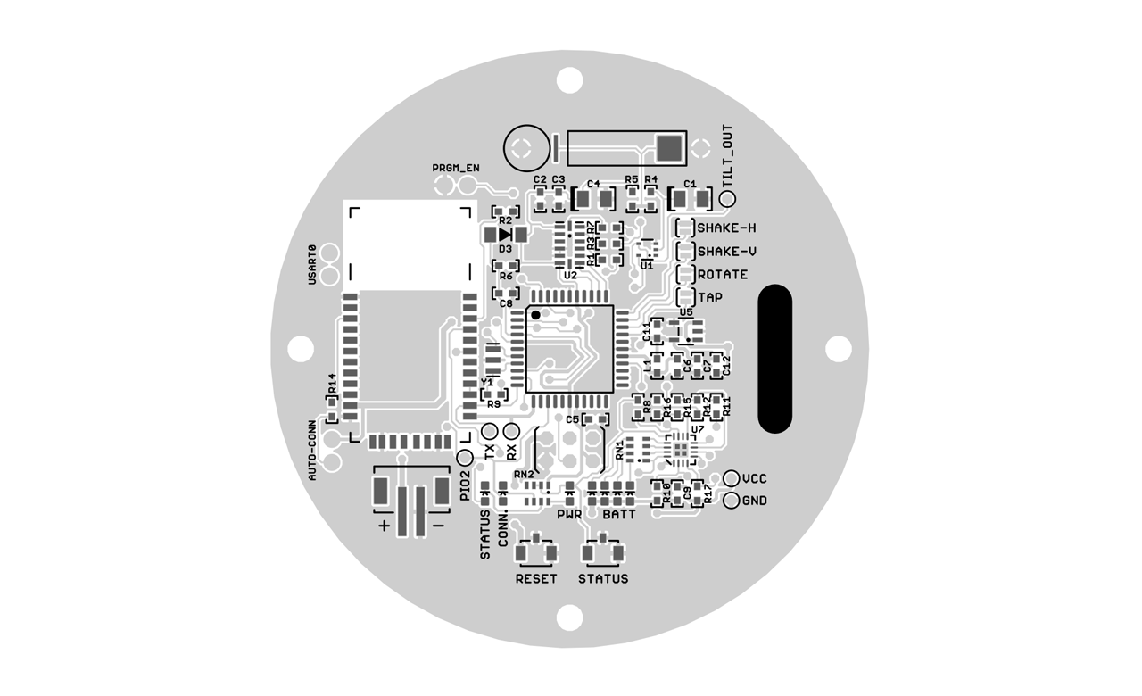
Before designing the circuit board, I laid out a set of requirements and my solutions to fill those requirements:
| Wireless | RN-42 Bluetooth Module |
| Easy PC Integration | Bluetooth HID standard compliant (computer sees a keyboard) |
| Long Battery Life | Low-power parts: ATmega324P microcontroller, ADXL345 accelerometer, TPS78233 LDO regulator. |
| Battery Meter | LM239 analog comparator (also low-power). |
| Must fit inside each cup | All SMD pards, QFN packages. |
| Low Price | One board supports all 4 controller types, selectable via four solder jumpers. |
In my first bit of analog circuit design, a quad comparator was used create a battery meter:
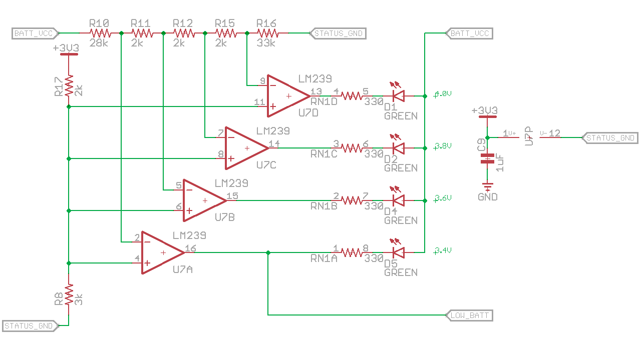
The exact resistor values were verified with a simulation ran in LT Spice.
Like pieces of a computer program, each module of circuit was prototyped and tested individually and as part of the whole system before we printed a few test boards. With these boards we tested assembly methods and made a few bug fixes before ordering the final 30 boards.
Process: Assembly & Quality Control
Since we’d be making 30 of these boards, I had to work out a way to streamline assembly as well as figuring out how to ensure that our interns could assemble the boards with minimal mistakes.
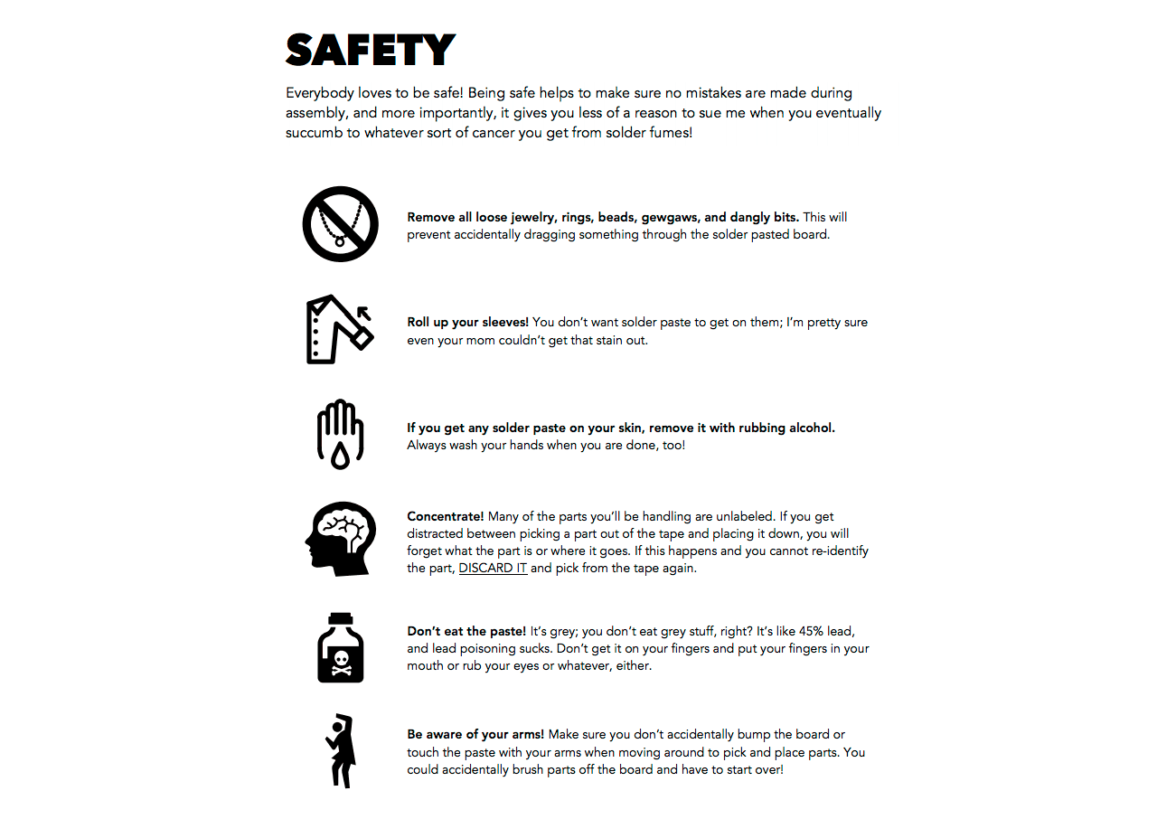
To solve both these problems, I created a short assembly manual, which included safety information, step-by-step assembly instructions, workspace tips, and a testing procedure.
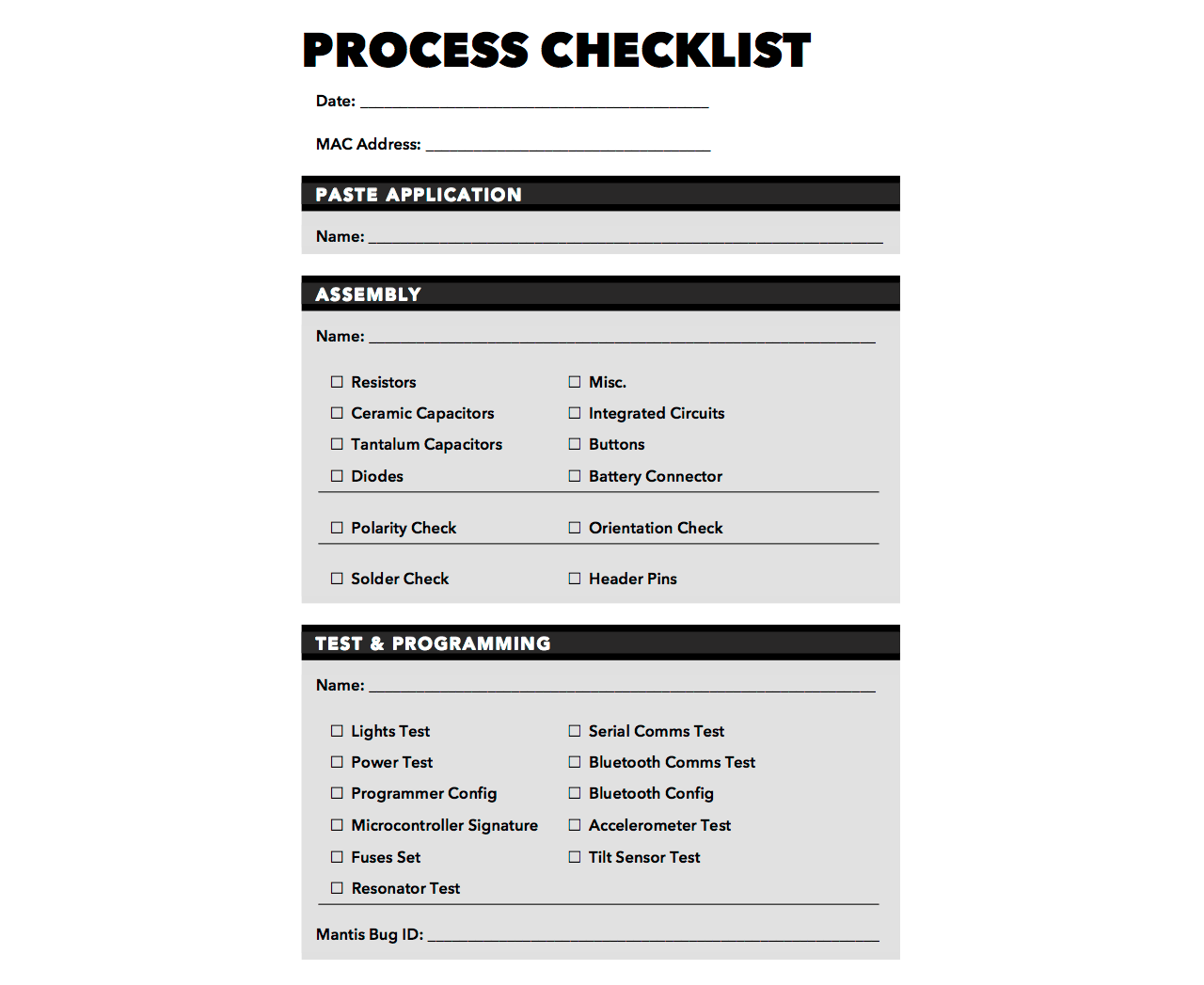
A checklist was included to track which steps had been completed by whom. Each board to be assembled was given one of these checklists, using the bluetooth module’s MAC address as an identifier to match the checklist to the board. Any issues in the assembly or testing process were to be logged in our company bug tracking system, and the bug ID was to be written on the board’s checklist.
In the end, about 75% of the boards were perfect first time. The remaining 25% suffered from problems mostly related to insufficient solder paste on the QFN parts. I had calculated that a 4mil-thick solder paste stencil would be perfect, but I was only able to find 3mil-thick mylar, and we didn’t have enough time to source the 4mil kind. In hindsight, the time we wasted fixing soldering issues could have been better spent waiting for 4mil-thick mylar to arrive.
Better ESD protection would have been good, too.
Shoutouts to EEVBlog and Mike’s Electric Stuff on youtube, and the fine folks at #electronics @ irc.freenode.net, except that one guy who told me my design was garbage.
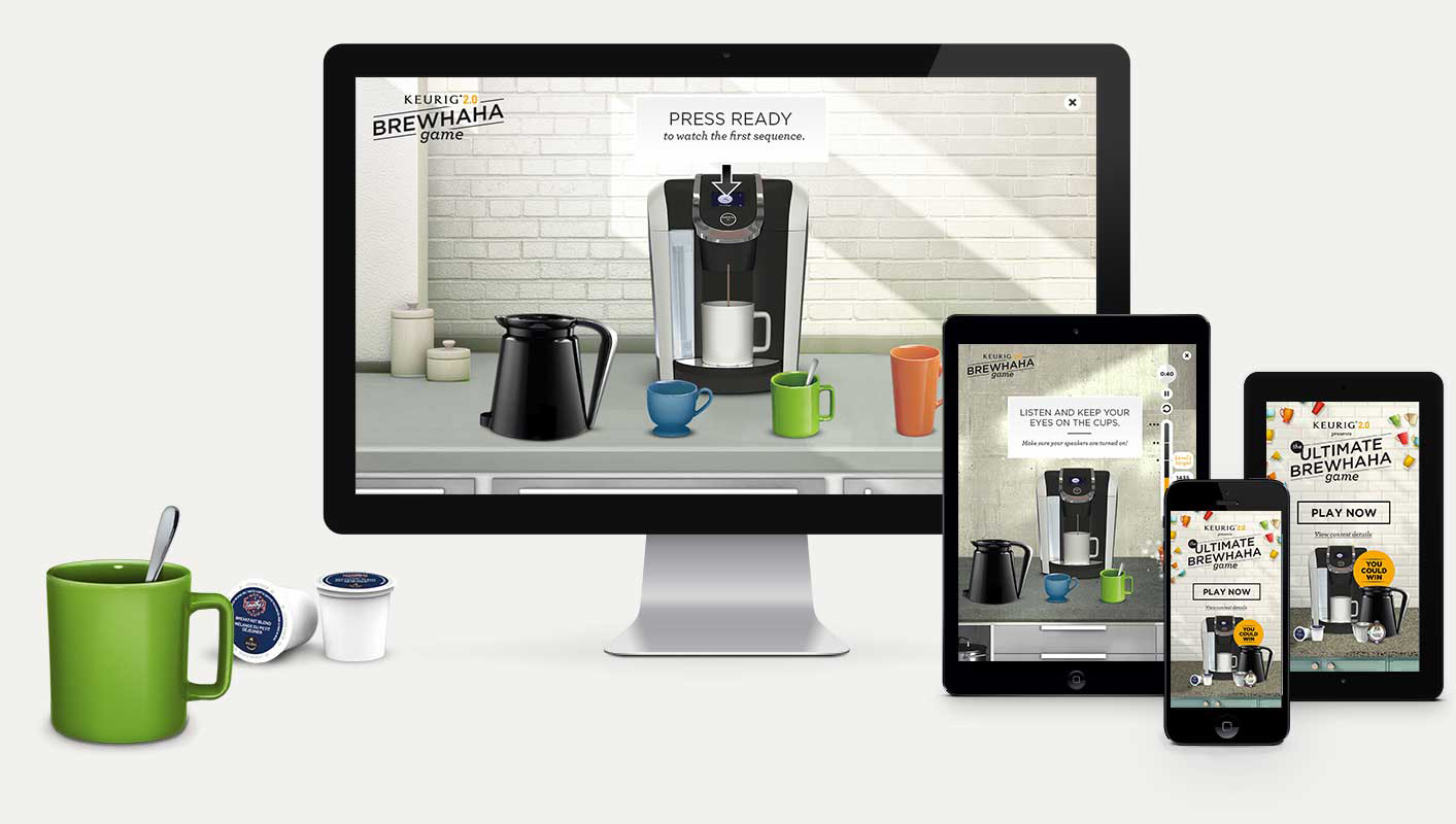
A Simon-esque memory game using physical coffee cup controllers, made for the release of the Keurig 2.0 coffee machine.
Players woud shake, tilt, and tap four colored mugs to complete the game at live events across Canada.
I was in charge of creating the circuitry for six sets of four wireless cup controllers. My electronics experience up until then was with hobbiest projects, so this was my first attempt at creating something “manufacturable”.
After the circuit board design was complete, I wrote an assembly manual to teach coworkers how to assemble and solder the board together.
Credits:
- Agency: Sidlee
- Studio: Bossa Digital
- Executive Producer: Hans Weiss
- Producer: Talia Greene
- CD: Andrezza Valentin
- Developer: Jeramy Morril
- Electronics: Jeremy Abel
- Assembly: Patrick Muth, Geetha Pedapati
- Art Director: Sarah Skapik
- Designer: Geetha Pedapati
- 3D: Hornet